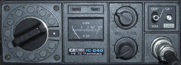
ICOM IC-240, FM transceiver, 10 W, 22 channels.
ICOM IC-240 MODS
ICOM IC-240, FM transceiver, 10 W, 22 channels.
INTRODUCTION
When the CW exam for a license expires, many used 2m transceivers are offered for sale. Ofteny even for an attractive price. For example, I came in possession of an ICOM IC-240 for € 15.50 (excluding shipping costs). Although an IC-240D has been present here for decades, I could not resist the temptation to buy a second one. Apart from a partly paintless cabinet due to mobile use, the set turned out to be OK after adjusting a few cores or trimmers. Such an additional device is always easy to experiment with, compare, test or make modifications. One can always fall back on the first rig.
|
Weight: 2 kg |
|
Frequency: 144 - 146 MHz |
|
Ouput: 10 W, 13.8 VDC/2 A |
|
Mode: FM (16F3) |
|
Channels: 22 |
|
Frequencies: programming with diodes |
|
SWR: protection for high SWR |
|
Spurious: 60 dB or more suppressing |
The most important features are («fig):
This device is mainly known in our country as IC-240D when it was equipped with six channels in the initial period of the D license. As soon as the owners were granted a C or A status, they often offered such a set for sale. In retrospect, that might be a shame, because the number of channels can be increased.
Quite a lot of this type must still be somewhere in a cabinet, in a basement or in the attic. Fix the thing because it is fairly easy to provide at least 48 channels. With the current decrease in activity on the 2 m band and with 48 FM channels one has sufficient choice of free frequencies. If you already have a 2 m set, then an IC-240 will become your "back up" or holiday set.
The original model IC-240 for the European market was equipped with 22 channels in the 25 kHz grid. A switch on the front panel was wired for a 1750 Hz tone or to reduce the output to 1 W. Output of 12.5 - 14.5 W is possible by adjusting trimmers of the final stage to maximum transmit power.
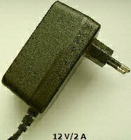
Due to, the absence of a power-guzzling display, this set uses only 2 A, so that a (fig») modern switched computer "adapter" is already sufficient as "power supply".
The transceiver is mechanically robust and the final stage is apparently over-dimensioned. I used it often to test and adjust antennas and to experiment with VHF PAs. The set is still intact!
48 CHANNELS, 25 kHz GRID
After the introduction of IC-240 many owners wanted more then 22 channels. Articles appeared and some ideas were really interesting because they could get more channels with not to much trouible. At the end of 1982 I equipped my set with 48 channels by combining the following modifications published in 1981 and 1982:
G8GEF's design ensures that repeater channels automatically are switched to the output frequency so that the DUP (LEX) & SIM (PLEX) switch on the front plate is not actually needed.
G4BLT's design makes it possible to utilize all the positions of the channel selector so that 24 frequencies are available.
GW4KJW's article is about programming the diode matrix with 50 kHz steps, so that the next higher 25 kHz channel can be selected with an additional switch or switch contact. So with DUP you have for example 145,500 and with SIM 145,525. When a repeater channel is selected, the set is automatically switched to the output frequency.
|
|
|
The part of the band 144,400 - 145,575 MHz that I have chosen, with channel 22 as the lowest frequency, seems a bit strange, but that was done to make it easier to remember channel numbers.
|
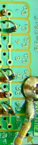
Chan * = 144.500, Chan 10 = 145.000 (1ste repeater) Chan 20 = 145.500 (call).
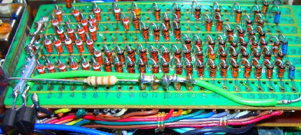
Calculation for example 145.500 MHz. Constantes are: 142.4 MHz en 25 kHz (145.500 - 142.4) : 0.025 = 124 124 = (64 + 32 +16 + 8 + 4) Location 5 diodes for 145.500 MHz: D6 (64), D5 (32), D4 (16), D3 (8), D2 (4) |
|
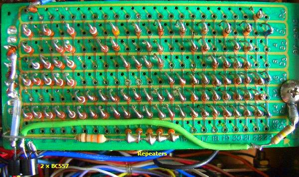
If you studies the images, then the modifications should not be too difficult. Note the correct "polarity" of the diodes relative to the print tracks. Reprogramming channels by removing or reinstalling diodes is a delicate job, because solder eyes are close together and holes are smaller than 1 mm. It is best to work with solder litze. If you have an IC-240 with 22 channels already programmed at the factory and you follow my channel layout, diodes of many channels can be cut.
CHANNEL 23
To activate channel 23, a wire must be installed from solder eyelet 23 on the PCB to the free contact of the channel switch.
CHANNEL 24
Channel 24 is achieved by a circuit with two PNP transistors, a 10 kOhm resistor and an interrupted wire. The transistor type is not critical. Cut the wire from the 9 V eyelet to the switch's contact and install the circuit with the transistors in between. I soldered them on the track side with the emitters soldere on the 9 V eyelet. That had been stable enough for decades to keep them on the spot.
The resistor (in my case 470 kOhm) must be grounded and I used for solder joint the screw that holds the PCB. Install a wire from collector T2 to the diodes for the frequency you have selected for channel 24. In my case 3 diodes for 145.500 MHz. They were soldered to the soldering pins of the PCB's connector. Make sure you select the correct contacts that correspond to D6 (64) to D0 (1).
For 10 repeater frequencies a diode was mounted on eyelets 10, 11, 12, 13 and 14. With a total of five diodes, you get 10 repeater channels. You are not bound by my choice of a channel and another corresponding eyelet to a position of the channel switch is possible, as long as the diodes at the top are connected to each other and you do not forget the 330 ohm resistor.
The following item is still future, because the outdated IC MC145151 has yet to be delivered. If all works, I expect that together with previous modifications there will be 96 channels available in the 12.5 kHz grid.
12.5 KHz GRID WITH 48 OR 96 CHANNELS?
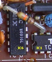
By replacing one IC it is possible to obtain a channel space of 12.5 kHz. This can be done by changing the dividend behind the oscillator of the running system. This is a part of two ICs TC5080P (IC1) and D4013C [IC6). Half of IC6 is a two-part divider followed by a programmable divider IC1 for the even divisions of 64 to 128. To get the 12.5 kHz grid now, it must be possible to arrange odd divisions of 129 to 287. This is possible if the functions of both ICs are taken over by one other programmable divider. The designer chose a present "antique" MC145151 of which only the divisor to be used is used. He wrote: "In order to avoid an overly complex conversion, remove IC1 and place a 16-pin IC socket in front of it. The 28-pin MC145151 is mounted on a separate PCB (eg Vero Board) that is constructed in such a way that it can be connected to the socket."
You can see the wiring in the image (fig»). With sophisticated fitting («fig) it seems to me that direct mounting on the track side is also possible. It is also possible to mount 12 solder pins on the component side in the vacated place and connect everything to the PLL board via wires.
A («fig) possible 10 kOhm resistor from IC6 pin 1 to IC1 pin 15 must be removed. A 220 pF capacitor is replaced by the socket (ex IC1) pin 15 to IC6 (D4013C) pin 3 on the track side.
With pin 11 of MC145151 you can choose for the 12.5 kHz or 25 kHz grid. To this end, a wire is soldered to the center contact of a switch so that a high voltage (12.5 kHz) or ground (25 kHz) can be switched for odd or even partial numbers. After these operations nothing needs to be changed anymore because you now have a choice of 44 channels. After making all the changes, I expect a total of 96 channels shoud be available, but that remains to be seen after the actual installation of an MC145151.
![]()
![]()